Using the electromagnetic induction principle, a relay is an automated switching device that regulates electrical circuits. When the control coil is energized, the generated electromagnetic force drives the mechanical contacts to actuate, achieving the switching (ON/OFF) of the controlled circuit. This feature of "controlling high power with low-power signals" is very crucial in solar power producing systems. It enables low-power control signals (typically from microprocessors or sensors) to safely manage high-power solar circuits.
Modern solar systems primarily employ two main technological branches of relays: traditional electromechanical relays and solid-state relays. Although electromechanical relays offer benefits such as low contact resistance and reduced cost thanks to their physical contact switching, they are prone to mechanical wear and arcing problems. Solid-state relays use semiconductor devices (such as thyristors, MOSFETs) to achieve contactless switching, boasting features like long lifespan, fast response, and no noise, but considerations for heat dissipation design and conduction voltage drop are necessary.
The solar power generation environment imposes special requirements on relays that differ from conventional industrial applications:
DC Voltage Tolerance: Solar arrays produce direct current (DC). DC arcs are more difficult to extinguish than AC arcs. Therefore, DC-specific relays require stronger arc-quenching capabilities and larger contact gap designs.
Wide Temperature Adaptability: Relays installed outdoors must withstand ambient temperature variations from -40°C to +85°C. Matching coefficients of thermal expansion and low-temperature startup characteristics are crucial.
Reverse Current Protection Design: Under partial shading conditions, the "hot-spot effect" may affect solar cell strings. Relays require protection capabilities to prevent reverse current flow.
High Cycling Life: Depending on system design, relays may perform tens to hundreds of switching operations daily. High mechanical and electrical endurance is fundamental to ensuring long-term system operation.
In large-scale solar power plants, relays shoulder the important responsibility of array partitioning management. By dividing the photovoltaic array into multiple independent sub-arrays, relays enable:
Localized Fault Isolation: When a sub-array experiences a ground fault, short circuit, or hot-spot effect, the relay can quickly isolate the faulty zone, preventing impacts on overall generation efficiency.
Maintenance Safety Power-Off: To ensure personnel safety, specific array circuits can be remotely or automatically disconnected during system maintenance.
Generation Optimization Control: In systems with multiple orientations, relays can intelligently switch combinations of different arrays based on sun position and load demand to maximize energy yield.
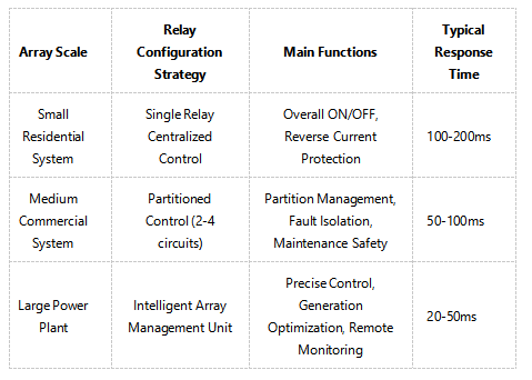
Table 1: Typical Relay Configuration Schemes for PV Array Management
Solar power systems are often used in harsh environments, so they require a specially designed relay.
Corrosion Protection: Coastal areas require relays with fully sealed structures and gold-plated contacts. This is because salt spray corrosion can cause contact failure otherwise.
High-Altitude Adaptation: The air's insulation strength decreases by around 10% for every 1000 metres of altitude increase. Products with higher creepage and clearance distances are needed for high-altitude areas (>2000m).
Vibration Resistance Design: Ground-mounted plants may be affected by strong winds, while vehicle or marine solar systems experience continuous vibration. Relays must pass the IEC 60068-2-6 vibration test standard.
Major global market certification requirements:
North American Market: UL508 Industrial Control Equipment Standard, UL1741 Inverter Standard, CSA Certification
European Market: CE Marking (including LVD and EMC Directives), IEC/EN 61800 Adjustable Speed Electrical Power Drive Systems Standard
Chinese Market: CQC Certification, GB/T 14598 Series Relay Standards
International: IEC 60255 Electrical Relays Standard, IEC 60947 Low-Voltage Switchgear and Controlgear Standard
Correct installation is the foundation for ensuring relay performance and must follow a systems engineering approach:
Thermal Management Installation:
Ensure sufficient heat dissipation space; maintain at least 20mm horizontal spacing between adjacent relays.
High-current relays (>100A) should be mounted on heat sinks, with active cooling added if necessary.
Avoid installing it directly above sources of system heat (e.g. inverter exhaust vents).
Wiring Specifications:
Separate control wires from controlled power lines with a minimum spacing of 300mm; cross them at a 90-degree angle.
Use standardized color coding for DC systems: red for positive, black for negative.
For reliable connections, use crimping or soldering instead of screw terminals, which can loosen over time.
Electromagnetic Compatibility (EMC) Design:
To prevent induced electromotive force from interfering with the control circuit when disconnecting, connect a freewheeling diode in parallel across the relay coil.
To reduce arcing and electromagnetic interference, connect an RC snubber circuit (e.g. a 47 Ω resistor in series with a 0.1 μF capacitor) in parallel across the contacts.
Establishing a three-level maintenance system maximizes system reliability:
Routine Inspection (Monthly):
Check contact status (e.g., signs of blackening, welding) through observation windows.
Perform infrared thermometry to detect connection point temperature rise (temperature difference from ambient should not exceed 40°C).
Listen out for any unusual sounds, such as buzzing, which may indicate coil issues, or abnormal clicking, which may indicate mechanical sticking.
Periodic Testing (Every 6-12 Months):
Functional Test: Various fault conditions should be simulated to verify the accuracy of relay actuation.
Contact Resistance Measurement: The measurement of closed contact resistance should be carried out using a micro-ohmmeter. The change compared to the initial value should not exceed 50%.
Insulation Resistance Test: Use a megohmmeter to measure the insulation resistance between the open contacts, which should be greater than 100 MΩ.
Predictive Maintenance (Based on Condition Monitoring):
Set up smart relays with built-in sensors to keep an eye on parameters such as contact wear, temperature, and actuation time.
Use trend analysis models to identify when to replace items before their performance degrades below a certain threshold.
Relays within the Battery Management System (BMS) undertake multi-dimensional protection duties, preventing damage to sensitive storage devices like lithium batteries:
Multi-Stage Voltage Protection: Relays execute staged actions when battery voltage reaches preset thresholds. For example, for NMC (Nickel Manganese Cobalt) batteries, charging current is first reduced at 4.15V/cell, and the charging circuit is completely cut off at 4.2V/cell.
Temperature-Linked Control: Working in coordination with temperature sensors, relays disconnect the circuit when battery temperature exceeds the safe range (typically 0-45°C charging, -20-60°C discharging).
Charge/Discharge Path Separation: To enhance system reliability and minimise mutual interference, high-quality systems use different charge and discharge relay topologies.
Pre-charge Control: During system startup, pre-charge relays and current-limiting resistors are used to avoid high inrush current from instantaneous capacitor charging.
Inverter protection, serving as the interface between the system and the grid, necessitates a multi-tiered relay architecture.
AC-Side Protection:
Islanding Effect Protection: In the event of a grid power failure, the relays must disengage from the grid within a specified timeframe (usually two seconds) to prevent 'island operation', which could endanger maintenance personnel.
Power Quality Monitoring: Monitors grid voltage and frequency, executing grid disconnect operations when values exceed permissible ranges (±10% voltage, ±0.5Hz frequency).
DC-Side Protection:
DC Arc Detection and Interruption: Uses dedicated Arc Fault Circuit Interrupter (AFCI) relays to detect and interrupt DC arcs that could cause fires.
Reverse Polarity Protection: It prevents damage to the inverter caused by wiring errors during installation or maintenance.
Redundant Protection Design:
Critical systems use a dual relay series configuration. Even if the primary relay fails, the backup relay can still provide basic protection, which makes the system much more available.
In solar-grid-generator hybrid power supply systems, relays form Automatic Transfer Switches (ATS) enabling intelligent energy dispatch:
Break-Before-Make Switching: It employs "break-before-make" logic control and the correct delay settings to prevent short circuits or back-feeding when switching between different power sources.
Priority Management: Can automatically select the optimal power source based on preset strategies. A typical strategy is: "Solar Priority → Battery Supplement → Grid Backup → Generator Emergency."
Load Shedding Control: It uses multiple relay circuits to classify loads as critical (e.g. lighting, communication systems and medical equipment) or non-critical (e.g. air conditioning and water heaters), ensuring a prioritised supply during energy shortages.
Quantitative calculation and systematic matching are essential when selecting relays for solar systems.
Voltage Level Selection:
DC System: Relay Rated Voltage ≥ System Maximum Voltage × 1.25 (Safety Factor)
AC System: Relay Rated Voltage ≥ System Voltage × 1.2 (Safety Factor)
For a 1000V DC PV system, select a DC-specific relay with a rated voltage of at least 1250V.
Current Capacity Calculation:
Continuous Current: The relay rated current must be equal to or greater than the maximum continuous operating current multiplied by 1.3.
Inrush Current: The relay must be able to withstand inrush currents that are 5–10 times higher than normal during inverter start-up or capacitor charging, which typically lasts 100–200 ms.
Electrical Life and Mechanical Life:
Electrical Life: The number of reliable switching cycles under rated load. Solar systems typically require at least 10⁵ cycles.
Mechanical Life: The number of switching cycles when there is no load, which is usually one order of magnitude higher than the electrical life.
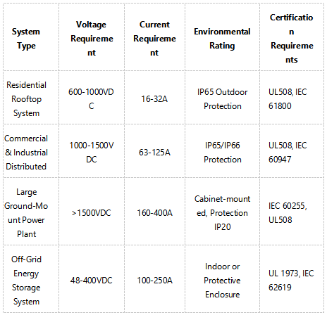
Table 2: Key Parameter Selection Guide for Solar System Relays
Solar power systems are often used in harsh environments, so they require a specially designed relay.
Corrosion Protection: Coastal areas require relays with fully sealed structures and gold-plated contacts. This is because salt spray corrosion can cause contact failure otherwise.
High-Altitude Adaptation: The air's insulation strength decreases by around 10% for every 1000 metres of altitude increase. Products with higher creepage and clearance distances are needed for high-altitude areas (>2000m).
Vibration Resistance Design: Ground-mounted plants may be affected by strong winds, while vehicle or marine solar systems experience continuous vibration. Relays must pass the IEC 60068-2-6 vibration test standard.
Major global market certification requirements:
North American Market: UL508 Industrial Control Equipment Standard, UL1741 Inverter Standard, CSA Certification
European Market: CE Marking (including LVD and EMC Directives), IEC/EN 61800 Adjustable Speed Electrical Power Drive Systems Standard
Chinese Market: CQC Certification, GB/T 14598 Series Relay Standards
International: IEC 60255 Electrical Relays Standard, IEC 60947 Low-Voltage Switchgear and Controlgear Standard
Correct installation is the foundation for ensuring relay performance and must follow a systems engineering approach:
Thermal Management Installation:
Ensure sufficient heat dissipation space; maintain at least 20mm horizontal spacing between adjacent relays.
High-current relays (>100A) should be mounted on heat sinks, with active cooling added if necessary.
Avoid installing it directly above sources of system heat (e.g. inverter exhaust vents).
Wiring Specifications:
Separate control wires from controlled power lines with a minimum spacing of 300mm; cross them at a 90-degree angle.
Use standardized color coding for DC systems: red for positive, black for negative.
For reliable connections, use crimping or soldering instead of screw terminals, which can loosen over time.
Electromagnetic Compatibility (EMC) Design:
To prevent induced electromotive force from interfering with the control circuit when disconnecting, connect a freewheeling diode in parallel across the relay coil.
To reduce arcing and electromagnetic interference, connect an RC snubber circuit (e.g. a 47 Ω resistor in series with a 0.1 μF capacitor) in parallel across the contacts.
Establishing a three-level maintenance system maximizes system reliability:
Routine Inspection (Monthly):
Check contact status (e.g., signs of blackening, welding) through observation windows.
Perform infrared thermometry to detect connection point temperature rise (temperature difference from ambient should not exceed 40°C).
Listen out for any unusual sounds, such as buzzing, which may indicate coil issues, or abnormal clicking, which may indicate mechanical sticking.
Periodic Testing (Every 6-12 Months):
Functional Test: Various fault conditions should be simulated to verify the accuracy of relay actuation.
Contact Resistance Measurement: The measurement of closed contact resistance should be carried out using a micro-ohmmeter. The change compared to the initial value should not exceed 50%.
Insulation Resistance Test: Use a megohmmeter to measure the insulation resistance between the open contacts, which should be greater than 100 MΩ.
Predictive Maintenance (Based on Condition Monitoring):
Set up smart relays with built-in sensors to keep an eye on parameters such as contact wear, temperature, and actuation time.
Use trend analysis models to identify when to replace items before their performance degrades below a certain threshold.
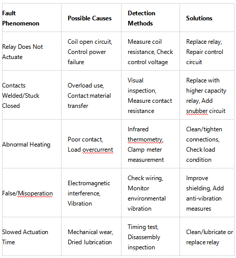
Understanding the potential failure modes of relays helps to design more reliable systems:
Contact Failure (Accounts for over 70% of relay failures):
Failure Modes: More resistance when you touch it, it sticks or welds together, and it doesn't work.
Effects: System performance degradation, complete failure, potential fire risk.
Mitigation: Derating use, regular maintenance, selecting high-quality contact materials.
Coil Failure:
Failure Modes: Open circuit, insulation breakdown.
Effects: Relay inoperable, loss of protection function.
Mitigation: The measures to be taken include voltage stabilisation, overvoltage protection and the selection of high insulation class products.
Mechanical Structure Failure:
Failure Modes: Jamming, spring fatigue.
Effects: Unreliable actuation, delay, or failure.
Mitigation: Select products with a high mechanical life to avoid frequent operation.
Relay technology is evolving towards intelligence, integration, and high performance:
Smart Relays: Incorporate microprocessors and communication interfaces (e.g. RS-485, CAN bus and Ethernet) to enable real-time status reporting, logging of operation counts, prediction of remaining life and deep integration with Energy Management Systems (EMS).
Hybrid Technology Relays: Combine the low conduction loss of electromechanical relays with the long life of solid-state relays, developing hybrid solutions suitable for solar systems.
New Material Applications: Employ novel contact materials (e.g., silver tin oxide, silver nickel alloy) to improve arc resistance; use high-temperature resistant engineering plastics to enhance environmental adaptability.
DC-Specific Technology Breakthroughs: Develop advanced technologies like magnetic blow-out, multi-break series connection, and vacuum arc quenching tailored to PV DC characteristics, improving DC breaking capability.
According to global renewable energy market research, the solar relay market shows strong growth momentum:
Market Size: The global solar relay market is projected to grow. It is expected to grow from USD 1.24 billion in 2023 to USD 2.17 billion by 2027. The market is expected to grow at a Compound Annual Growth Rate (CAGR) of 11.8%.
Regional Distribution: The Asia-Pacific region is the largest market (45% share), driven mainly by China, India, and Japan. Renewable energy policies are driving rapid growth in the North American and European markets.
Technology Trend: It is expected that the market share of smart relays will increase from less than 20% to over 35% by 2027, establishing them as the mainstream choice.
Standard Evolution: IEC and UL are developing relay standards. These are specifically for PV applications. This further enhances product standardisation and interchangeability.
The development of virtual power plants (VPPs) and microgrid technologies means that relays are playing new roles in system-level integration:
Grid Service Support: Through fast and precise switching control, help solar systems provide auxiliary services like frequency regulation and voltage support.
Adaptive Protection: Relay protection settings can automatically adjust during microgrid grid-connected/islanded mode transitions, adapting to different operating conditions.
Coordinated Control: Multiple geographically dispersed relays coordinate actions via communication networks, achieving regional-level PV generation optimization and fault handling.
Though small, relays are the cornerstone for the safe, efficient, and intelligent operation of solar power generation systems. Evolving from simple circuit switches to key nodes in smart grids, relay technology has developed into a comprehensive discipline integrating power electronics, materials science, communication technology, and control theory.
In solar system design and implementation, the selection and application of relays must be guided by a full lifecycle perspective: When considering this, make sure you take into account not only the initial cost and whether the technical parameters are compatible, but also how reliable it will be in the long term, how easy it will be to maintain and whether it can be scaled up or down as required. The correct relay solution can significantly reduce system failure rates, extend core equipment lifespan, and improve energy output efficiency.
As the global energy transition accelerates and solar power costs continue to decline, relay technology will evolve towards higher voltage levels (2,000 VDC and above), larger current capacities and greater intelligence. For system designers, installers, and operators, a deep understanding of relay technology and mastery of its application essentials will become a key competency to stand out in the competitive renewable energy market.
In the future, relays will no longer be passive components that simply execute switching actions. They will become intelligent sensing and execution terminals for solar power generation systems, integrating advanced technologies such as digital twins and AI-powered predictive maintenance. This will lay the foundations for creating a safer, more efficient and more reliable global renewable energy infrastructure.