In electrical engineering, relay sensors operate as the "invisible hand," subtly overseeing and precisely regulating all power activations and deactivations, ranging from vast industrial production lines to compact smart home devices. Their essence is an automated device that utilizes electromagnetic, solid-state, or thermal principles to convert an input control signal (low current, low voltage) into a mechanical or electronic switching action, thereby safely and reliably controlling an output circuit (high current, high voltage, or different potential). A deep understanding of their diverse working principles is not only a fundamental skill for electrical engineers in system design and component selection but also the key to quickly locating issues and implementing precise strategies when facing complex system failures. This article aims to systematically dissect seven core working principles of relay sensors and extend the discussion to their application, selection, and troubleshooting logic, building a solid professional knowledge framework for you.
Electromagnetic actuation is the soul of most traditional electromechanical relays. Its operation is a precise conversion of electrical energy, magnetic energy, and mechanical energy.
When control current flows through the coil wound around the iron core, a magnetic field is established around the core. The strength (H) of this magnetic field is proportional to the product of the number of coil turns (N) and the current (I) (i.e., the ampere-turns, NI). The iron core (usually forming a closed magnetic circuit with the yoke) greatly concentrates and enhances the magnetic flux (Φ). When the magnetic force is sufficient to overcome the preload force of the return spring, it attracts the armature made of soft magnetic material. The armature's motion is directly sent via an insulating bracket to the moving contact, resulting in its rapid closure or separation from the fixed stationary contact, thus finalising the connection or disconnection of the main circuit. After the coil is de-energized, the magnetic field disappears instantaneously, and the spring force pulls the armature and the moving contact back to their initial positions, achieving reset.
Coil Parameters: DC resistance and inductance determine the relay's pull-in/release time, power consumption, and requirements for the driving circuit. A high-inductance coil produces a significant back electromotive force (EMF) upon activation.
Magnetic Circuit Design: The composition and spacing of the iron core and yoke significantly impact the reluctance and efficiency of the magnetic circuit, thus affecting sensitivity and power consumption.
Contact Pressure and Material: The contact pressure ensured by spring design guarantees the stability of contact resistance, while the choice of contact material (e.g., silver cadmium oxide, silver nickel alloy) is decisive for arc suppression, anti-welding, and conductivity.
The two primary purposes of the relay, electrical isolation and power amplification, are based on this idea.
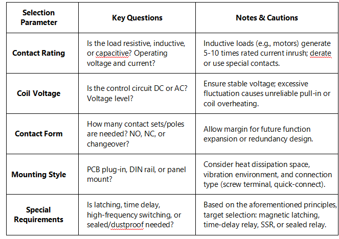
Contact configuration is the direct manifestation of a relay's function. It predefines the default state of the circuit in the absence of a control signal and is the starting point for system safety logic design.
Normally Open Contact (Form A): Open by default, closes after relay actuation. The preferred choice for "start" functions like activating motors or turning on lighting.
Normally Closed Contact (Form B): Closed by default, opens after relay actuation. Commonly used in safety circuits, emergency stops, or status indication (e.g., an indicator light turns off when equipment is running).
Changeover Contact (Form C): This is a common moving contact that can switch between one normally closed contact and one normally open contact. It offers great flexibility and can be used to achieve interlock control, signal switching, or special sequences like "make-before-break."
In safety-critical systems, such as Emergency Stop (E-Stop) circuits, Normally Closed contacts are typically mandated. Any issue that results in circuit interruption (e.g., wire fracture, relay coil deactivation, contact malfunction) will promptly transition the system into a safe shutdown state, in accordance with the "fail-safe" principle. This contrasts sharply with designs using Normally Open contacts, which require active energy to trigger the safe state.
Latching relays solve the energy consumption problem of traditional relays requiring continuous power to maintain state, achieving single-pulse control and bistable state holding.
This is the most common latching type. Its interior contains not only an electromagnetic coil but also one or more integrated permanent magnets. In the initial state, the attractive force of the permanent magnet on the armature holds it stable at position A (e.g., corresponding to the normally open contact being closed). When the coil receives a forward pulse current, the electromagnetic force combines with the permanent magnet force, driving the armature to overcome mechanical resistance and move to position B, where it is held. At this juncture, even with the coil de-energised, the magnetic pull from the permanent magnet secures the armature securely in position B. To reset, simply apply a reverse pulse current to the coil. The induced electromagnetic force negates and surpasses the permanent magnet force, retracting the armature to position A. This mechanism consumes minimal energy, acting only briefly during state transitions, making it particularly suitable for solar-powered remote meters, smart gas meters, water meters, and analogous applications.
This method typically involves physically locking the armature or contact mechanism with an independent mechanical latch (e.g., ratchet, detent) after actuation. The reset necessitates an additional independent reset coil to be activated in order to produce the pulling power required for unlocking or manual button operation. Its benefit resides in the unequivocal stability of condition, impervious to external magnetic fields, and it is frequently employed in power distribution apparatus necessitating great dependability and explicit status signalling.
Time delay relays upgrade "instantaneous response" to "planned response" and are the core of coordinating sequential actions of multiple devices in automated processes.
On-Delay (Delay-on-Make): Timing starts when the coil is energized; the contacts actuate after the timing period ends. The contacts reset instantaneously when the coil is de-energized. Used for motor star-delta starting (star connection first, then switch to delta after delay) and automatic equipment startup after preheating.
Off-Delay (Delay-on-Break): The contacts actuate instantaneously when the coil is energized. Timing starts when the coil is de-energized; the contacts reset after the timing period ends. Utilised for the deferred deactivation of cooling fans following the cessation of large fans and for the ongoing operation of the lubrication system post main unit shutdown.
Interval Delay and Cycling Delay: More complex types that can generate fixed-period or duty-cycle adjustable pulse outputs.
Early Mechanical/Pneumatic Types: Utilized air throttling through small orifices or clockwork escapement mechanisms. Adjustment was inconvenient but they had strong anti-interference capability.
Modern Electronic Types: The core is an RC integration circuit or crystal oscillator + counter. By adjusting a variable resistor (potentiometer) or digital settings to change the charge/discharge time constant or count value, high-precision, wide-range delay settings are achieved. Digital time relays can also be remotely set and monitored via buses (e.g., Modbus).
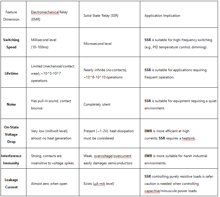
Solid-state relays completely abandon mechanical moving parts, achieving a "quiet" transformation using semiconductor switching devices.
An SSR consists of three parts: the input circuit (opto-coupler, achieving high-voltage/low-voltage isolation), the drive circuit (triggering the TRIAC or MOSFET), and the output switching device (bidirectional TRIAC for AC, MOSFET for DC). When a small voltage signal is applied to the input terminal, the LED in the opto-coupler emits light, the photosensitive element conducts upon receiving light, triggering the subsequent circuit to saturate and turn on the output device, energizing the load.
Protective relays integrate sensing and actuation, providing close-in protection for lines or motors.
The core consists of a bimetallic strip, which is composed of two metals with dissimilar coefficients of thermal expansion that are linked together. The load current flows through a heating element on it or directly through the strip itself, generating heat. Under overload conditions, thermal accumulation induces the bimetallic strip to flex towards the side exhibiting a lower expansion coefficient, thereby activating the trip mechanism to open the normally closed contact within a matter of seconds to minutes. Its "inverse-time characteristic" (higher current leads to shorter trip time) perfectly simulates the heating characteristics of a motor, making it a classic solution for motor overload protection. After cooling, the bimetallic strip returns to its original shape, allowing for manual or automatic reset.
This comprises an electromagnet coil linked in series with the primary circuit. When a large current such as a short circuit occurs (typically 5-10 times the rated current or more), the electromagnet generates a huge attractive force, instantly (within tens of milliseconds) pulling in the iron core, directly triggering the mechanical mechanism to open the contacts. Its action is instantaneous, not dependent on heat accumulation, and is designed specifically for quickly cutting off lethal short-circuit currents.
When cutting off current in an inductive coil (like a relay coil, solenoid valve coil), the magnetic field energy (½LI²) has nowhere to release, generating a reverse voltage spike of hundreds or even thousands of volts, which can cause fatal breakdown of the transistor or integrated circuit driving it.
Freewheeling Diode: A diode is connected in reverse parallel across the coil terminals (cathode to positive supply). When de-energized, the coil current forms a freewheeling path through the diode, and the energy is slowly dissipated as heat. This is the most economical and effective protection scheme for DC circuits, but it slows down the coil current decay, slightly delaying relay release.
RC Snubber Circuit (Resistor-Capacitor Absorption): A series-connected resistor and capacitor are connected in parallel across the coil terminals. The capacitor absorbs energy, and the resistor damps oscillations. Appropriate for AC/DC applications, exhibits reduced influence on release time, although entails a more intricate design.
Varistor (MOV): A voltage-sensitive nonlinear resistor whose resistance drops sharply when the threshold voltage is exceeded, clamping the spike voltage to a safe value. Often used for AC coils or applications with strict voltage spike limitations.
Application Panorama: Relay sensors have permeated every corner. In smart homes, relay modules perform commands from mobile applications to regulate lighting and curtains. In electric vehicles, high-voltage relays manage the critical connection between the traction battery pack and the drive system. In photovoltaic inverters, relays ensure safe isolation between the equipment and the grid before grid connection.
Safety First: Disengage any pertinent power sources. Discharge any possibly substantial capacitors.
Visual and Olfactory Inspection: Look for obvious signs like blackened/eroded contacts, melted coil insulation varnish, deformed housing.
Coil Side Test: Use a multimeter to measure coil resistance. Infinite resistance signifies an open circuit; minimal resistance denotes a short circuit. Compare with the nominal value specified in the datasheet (usually with a tolerance of ±10%).
Contact Side Test:
Static Test (De-energized): Measure if the NO/NC contact continuity matches the nominal state.
Dynamic Test (After Energized Actuation): Measure the contact resistance between closed contacts. It should be far less than 1 ohm. Excessive, unstable resistance, or accompanying voltage drop indicates eroded/aged contacts.
Peripheral Circuit Verification: Check if the driving transistor/IC is intact, if the suppression circuit (diode, etc.) is reversed or blown, and if the supply voltage meets specifications.
Substitution Method Verification: When conditions allow, replace with a known-good relay of the same model for testing. This is the fastest method for fault isolation.
Mastering these seven fundamental operational concepts enables you to comprehend not just the relay's "limbs" but also its "nerves" and "reflex arcs." In the era of the Internet of Things and Industry 4.0, relay sensors are evolving towards integration (e.g., smart relays integrating protection, measurement, and communication functions), networking (relay modules supporting IoT protocols), and miniaturization (micro and sub-miniature relays for high-density PCBs). However, the fundamentals remain unchanged. The fusion and complementarity of classical electromagnetic principles and emerging semiconductor technologies will continue to propel this ancient yet vital technology towards renewal. Only by being rooted in solid principles can one flexibly respond to myriad future changes and design electrical control systems that are both reliable and innovative.